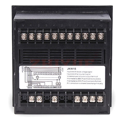
Product Description
JKW series intelligent low voltage reactive auto compensation controller (abbr. Controller) is the special device for compensating reactive power for low voltage distribution system. Its sampling physical quantity is reactive power,with various specifications of 116 step dynamic output(JKWD15, JKWD2C) and static output(JKW15S JKW2C.. JKW1 BFs JKWIBJx JKW3B, JKW2B) etc, as well as with characteristics of novel design, multifunction, fine control performance and high reliability etc. It is at the leading position among similar products in domestic market and supplies a brand new device for distribution automation.
Features:
1. Adopt AC sampling technology.
2. Use fundamental wave power factor and fundamental wave reactive power as control physical quantities, with high control accuracy, no switching oscillation, and insensitive to harmonics.
3. The control parameters are all digital operation, easy to use, one step in place, and data is not lost after power failure.
4. The automatic optimization control scheme is adopted to reduce the number of switching and improve the service life of the system.
5. Strong anti-interference ability, can resist the 2000V interference pulse input directly from the power supply, without crashing or losing data, stable and reliable operation.
6. Digital display of grid power factor, reactive power, voltage, current (primary side), and control parameters.
7. It has two working modes: manual operation and automatic operation, which is convenient for users to install and debug.
8. It has the function of judging and displaying over-voltage and under-voltage and quickly cutting off the capacitor bank to prevent the capacitor bank from operating under over-voltage conditions.
9. With optional switching and oscillating locking function (users need to indicate when ordering).
10. With the optional function of delaying 200 seconds from the time of removal of a single group of capacitors to the time of input, the capacitor bank has sufficient discharge time after removal, and reduces the impact on the power grid when the capacitor is re-input (users need to specify when ordering) .
11. The input resistance of the current sampling signal is less than 0.05 ohm, which can be directly taken out of the metering loop.
12. There are two compensation modes of power factor and reactive power.
13. The instruction manual provides a large number of troubleshooting methods to facilitate installation and debugging.
Technical Parameters:
1. Basic parameters:
Rated voltage: AC380/AC220V ±10%
Rated current: AC0-5A
Rated frequency: 50Hz±5%
2. Control parameters:
Sensitivity: 100mA
Target COSφ preset: 0.70-0.99; step size 0.01; factory preset 0.98
Switching delay: 1-250S
Overvoltage protection: 380-500/230-260V; step length 1V; hysteresis 6V
Undervoltage protection: 340V/180V; hysteresis 6V
CT changes: 50/5A-4000/5A; step length 1; factory preset 500/5A
 Your message must be between 20-3,000 characters!
 Please check your E-mail!
  Your message must be between 20-3,000 characters!
 Please check your E-mail!


